How Can Grid-Forming BESS Improve Data Centre Grid Stability and Flexibility?


On paper, a data centre looks like a steady load. In practice, it can behave like a switch. When a grid fault dips the voltage, UPS systems transfer to batteries, and the load disappears from the network. In Virginia in 2024, this caused the sudden removal of about 1,500 MW [1]. For a transmission operator, this represents an event of generation size on the demand side, while for a developer it turns into a connection condition. The article adopts a study-based approach to the subject of grid-forming BESS for data centres: not an explanation of what the technology is in principle, but rather which engineering checks determine whether it works on an actual site.
Where the Risk Really Comes From
Two different behaviours create the problem, and they need different answers.
The first is transfer behaviour. An uninterruptible power supply data centre design is built to protect servers, so it disconnects from a disturbed grid quickly. Common uninterruptible power supply uses (ride-through, conditioning, short backup) never required it to think about the network.
The second is training-load behaviour. AI clusters swing between high and low power in repeating cycles, and utilities are specifying limits on oscillation in bands such as 0.1–20 Hz [2].
A load step is a one-off event needing energy for seconds. An oscillation is continuous and needs fast, repeated cycling. Confusing the two leads to wrongly sized storage.
Grid-Forming in Plain Engineering Terms
An inverter which follows the grid is one that acts as a current source and keeps up with the grid. An inverter which forms the grid acts as a voltage source behind an impedance, maintaining the voltage and supplying synthetic inertia within the constraints of its current output [3]. Although the fault current of such an inverter is still limited, this limit is much lower than that of a synchronous machine and influences all the design decisions that follow.
Britain has already put this into practice, with NESO's Stability Pathfinder treating grid-forming batteries as a stability resource [4].
A Five-Stage Study-to-Site Pathway
Most guides stop at the concept. Projects succeed or fail in engineering sequences. This is the pathway we recommend.

Stage 1: Define the Disturbance Envelope
Begin with the power system studies rather than looking at the battery datasheet; determine the short-circuit level, identify plausible fault locations, establish the depth of the voltage dip and the reclosing behaviour at the point of connection. Only then should you get the UPS vendor's transfer thresholds, since without them you cannot know how much load can be lost.
Stage 2: Decide What the Battery Must Do
This is where grid-forming BESS for AI data centre power stability is defined as a duty, not a product. Each duty drives a different specification:
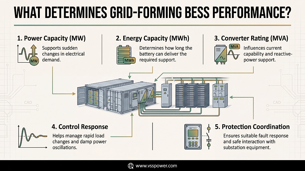
Load-step cushioning: MW headroom for seconds to minutes
Oscillation damping: fast cycling and controller bandwidth
System strength: PCS current capability in MVA
In many cases, the converter MVA rating, not the MWh capacity, decides the outcome.
Stage 3: Coordinate Protection and Control
Grid-forming current limiting must coexist with overcurrent protection at the substation. The BESS controller can also interact with rectifier controls inside the facility. Measurement and communication delay matters too: a 2026 conference paper tested its impact on smoothing performance in grid-forming battery control [5]. For sites taking a high voltage power supply, protection settings and substation design should be agreed with the control philosophy, not after it.
Stage 4: Prove It With Validated Models
Network operators require evidence, which consists of RMS and electromagnetic transient models that have been verified using the actual controller, together with a compliance matrix relating to the applicable code. In Europe, the draft NC RfG 2.0 contains grid-forming requirements for storage, with national implementation to come [6]. The relevant standards usually involve IEC 62040-3, IEC 62933 and IEEE 2800. Make sure you confirm the most recent editions.
Stage 5: Test and Commission
The factory and site acceptance tests should include inspections of mode changes, fault ride-through behaviour and control response, and these should be observed where necessary. It is a risk if a control function has never been tested at the site, not a feature.
Stage | Key question | Typical output |
1. Disturbance envelope | What can the grid and UPS do? | Study report, fault list |
2. Duty definition | What must storage deliver? | Performance specification |
3. Protection and control | Do systems interact safely? | Settings, control philosophy |
4. Modelling and compliance | Can we prove behaviour? | Validated models, matrix |
5. Commissioning | Does it work on site? | Test records |
An Illustrative Example
Let us consider a hypothetical campus with a capacity of 80 MW that is connected to a weak 132 kV node. It has been found that a fault could cause the majority of the load to be switched off for a few hundred milliseconds. The worry of the operator is the increase in voltage that follows. A grid-forming battery, which is rated for the load step, and equipped with a converter capable of providing fault-level support, can be evaluated in relation to that specific situation. The design issue then takes the form of specific measurable criteria: the amount of voltage rise, the speed of this rise, and the margin provided. This is an example based on a worked-through case and not actual project data.
Pitfalls Worth Avoiding
Setting the size based on MWh rather than on duty.
Considering the battery and the UPS as two separate projects.
Going to the network operator once the design has been finalised.
Submitting unvalidated models.
Delaying the control testing until the week before.
Regional Notes
In the UK, around 140 data centre projects are in the transmission queue, so flexible connection options are being discussed [7]. Across Europe, expect each country to interpret grid-forming principles in its own way. In the Middle East and India, high temperatures and weaker local grids make thermal design and early grid-forming planning especially important.
Benefits of Battery Energy Storage for Data Centres
The benefits of battery energy storage for data centres can include smaller grid reinforcement, phased energisation, steadier power quality and potential eligibility for stability services. Treat these as design goals to verify in studies, not guarantees. Whether you are a utility, EPC contractor or developer comparing green energy companies in the UK, ask who can carry the work from studies to commissioning.
How VSS Power Supports This Work
VSS Power Engineering Services Ltd. is a UK-registered team with operations in the UK and India, founded in 2014. Its engineers work on design, engineering, testing and commissioning of high-voltage substations and power plants, plus protection, control and grid integration. That span is what a BESS (battery energy storage system) connection needs: studies, substation design, protection and control, and site proof.
Conclusion
Grid-forming storage can help data centres support the grid, but only if duty, studies, protection, and testing are all aligned. If you're considering a connection or storage project, talk to VSS Power to get a study-led approach.
FAQs
1. What is grid-forming BESS for data centres?
It is a battery storage system that acts as a voltage source, so it can help hold voltage and provide inertia at a data centre’s grid connection [3].
2. How is it different from a data centre UPS? A UPS protects the IT load and can fall out quickly as a force of an imbalanced grid, such as the 1,500 MW Virginia event [1]. Storage supports the network side instead, with grid-forming capabilities.
3. Can it reduce AI training power swings?
Yes — but only if done with the right duty factor. Load steps require seconds for energy. Oscillations, in contrast, may be mediated by swift, repetitive cycling [2].
4. What studies are needed before connection?
Begin by examining the short-circuit level, likely fault locations and the depth of voltage dips. Next, prepare validated models and a compliance checklist, then carry out acceptance tests at the site.
5. Which codes and standards apply?
In Britain, NESO’s Stability Pathfinder led the way [4]. In Europe, the draft NC RfG 2.0 covers grid-forming storage [6]. Also check IEC 62040-3, IEC 62933 and IEEE 2800.
References


Comments