Earthing System Design for High Voltage Substations: A Complete Guide
- VSS Power

- 1 day ago
- 6 min read

As power grids expand and renewable energy sources penetrate, substation electrical safety has never been more important. High-voltage substations are vital to modern infrastructure, as they manage large fault currents and deliver reliable power.
A properly engineered earthing system design substation solution plays a vital role in personal protection, equipment protection, and network assurance. Grounding Issues: If not properly controlled, ground faults, lightning strikes, and switching surges can result in hazardous electrical conditions.
Utilities, wind and solar developers, industrial sites, and power system consultants must all invest in robust grounding systems to ensure long-term safety and compliance.
What Is an Earthing System in a High Voltage Substation?
The earthing system allows fault current to flow to earth with minimal resistance, keeping personnel, equipment, and buildings safe from dangerous electrical conditions.
The primary objectives include:
Personnel safety
Equipment protection
Lightning protection
Fault current dissipation
System stability
Regulatory compliance
A typical substation earthing system includes the following:
Earth grid conductors
Ground rods
Earth mats
Bonding conductors
Equipment grounding connections
Fence grounding systems
Lightning protection integration
A well-engineered grounding system ensures that fault currents are conducted along predetermined paths and not through human beings or the equipment.
Why Earthing System Design Substation Projects Are Critical
High-voltage substations may experience fault currents from 10 kA to over 80 kA, depending on network configuration.
During a fault event:
Massive electrical energy is released.
Ground potential rise (GPR) occurs.
Dangerous touch voltages may develop.
Step voltages can threaten nearby personnel.
There is also a higher chance of equipment damage.
A robust grounding design helps:
1. Protect Human Life
The main goal is to eliminate the risk of electric shock.
Effective grounding minimises:
Touch voltage risks
Step voltage hazards
Transfer potential issues
2. Improve Equipment Reliability
Enhance The Reliability Of Equipment
Transformers
Circuit breakers
Protection relays
Control systems
Communication equipment
3. Ensure Regulatory Compliance
Most projects must comply with:
IEEE Std 80
IEC 61936
BS EN Standards
Utility-specific requirements
4. Support Renewable Energy Integration
With the rapid development of renewable energy businesses in the UK, particularly in wind and solar power, substation grounding systems need to be able to cope with new fault conditions.
Key Components of a Substation Earthing System
Earth Grid
Earth grid forms the base of the grounding system.
Functionality includes:
Dissipation of fault current
Equalisation of surface potential
Reduction of touch voltage
Ground Rods
Ground rods decrease earth resistance by going into more resistive layers of the soil.
Advantages are:
Reduced grounding resistance
Better fault current distribution
System stability improvement
Bonding System
Bonding keeps all metallic structures at the same electrical potential.
Typically bonded equipment includes:
Transformers
Switchgear
Steel structures
Cable trays
Fences
Surface Layer Materials
Materials such as crushed rock add to surface resistance and reduce shock hazards.
Typical materials:
Crushed granite
Gravel
Resistant aggregates
Earthing System Design Process
Step 1: Soil Resistivity Survey
Design begins by conducting soil resistivity tests.
Popular test procedures include:
Wenner Four-Probe Test
Schlumberger Test
Knowledge of soil properties enables the determination of:
Ground Resistance
Grid Size
Rod Depth
Step 2: Fault Current Analysis
Calculations include:
Maximum fault current
Time of fault
Effect of ground fault
Fault studies are extremely important to ensure safety in the design.
Step 3: Ground Grid Layout Design
Engineers determine:
Grid size
Conductor spacing
Locations of ground rods
Bonding locations for equipment
Step 4: Ground Potential Rise Analysis
Ground Potential Rise (GPR) calculations determine possible voltage increases in case of faults.
The goal is to ensure safe voltages throughout the entire site.
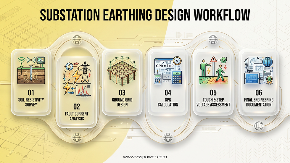
Step 5: Touch and Step Voltage Assessment
Engineers compare the computed values to the specified limits. If limits exceed standards, mitigation options are:
Additional conductors
More ground rods
Surface treatment enhancements
Step 6: Detailed Design Documentation
For the most part, deliverables for the detailed design consist of:
Earthing layout drawings
Cable schedules
Grounding calculations
Compliance reports
Construction details
An experienced UK substation design engineer ensures that all calculations are to the appropriate standards.
Typical Earthing Design Parameters
Parameter | Typical Range |
Soil Resistivity | 10–5000 Ωm |
Ground Resistance | Below 1 Ω |
Fault Current | 10–80 kA |
Grid Conductor Depth | 0.5–1.0 m |
Grid Spacing | 3–10 m |
Ground Rod Length | 3–20 m |
Actual values depend on site-specific conditions.
Industry Applications
Utility Substations
Transmission and distribution utilities depend on good grounding systems for the safe and reliable operation of their networks.
Renewable Energy Projects
Many renewable energy companies in the UK require advanced grounding systems for:
Solar farms
Wind farms
Battery Energy Storage Systems (BESS)
Hybrid renewable energy facilities
Industrial Facilities
There are some industries where the electrical infrastructure is high-voltage, and to really get that earth-touching solution, you need robust grounding.
These include:
Factories
Data centers
Mining operations
Oil and gas platformês
Water processing plants
Infrastructure and Transportation
Earthing systems are critical for:
Railway substations
Metro systems
Airports
Ports and logistics hubs
Common Challenges and Solutions
High Soil Resistivity
Challenge
When soil does not conduct electricity well, grounding resistance goes up.
Solution
Deep ground rods
Ground enhancement compounds
Larger grid areas
Limited Site Space
Challenge
Urban substations often have limited space.
Solution
Optimised conductor arrangements
Vertical grounding electrodes
Advanced modelling software
Rising Fault Levels
Challenge
Expanding the grid can raise fault current levels.
Solution
Periodic system reviews
Upgraded conductor sizing
Enhanced grounding networks

Corrosion
Challenge
Grounding conductors can wear out over time.
Solution
Corrosion-resistant materials
Regular inspections
Protective coatings
Best Practices for Earthing System Design
To get the best results:
1. Carry out the site investigation in soil detail.
2. Perform accurate fault current calculations.
3. Comply with IEEE, IEC, etc. standards.
4. Calculate touch and step voltage.
5. Combine lightning protection systems.
6.Think ahead.
7. Confirm results with more sophisticated tools.
8. Perform routine tests and maintenance.
Adhering to the above guidelines enables the system to be safer, more dependable, and longer-lived.
Future Trends and Innovations
The power industry is changing quickly, which brings new opportunities for grounding system design.
Digital Grounding Simulations
Advanced software enables:
3D modelling
Real-time analysis
Enhanced accuracy
Smart Substations
Digital substations require grounding systems that support:
Intelligent electronic devices
Communication networks
Cyber-physical infrastructure
Renewable Energy Expansion
The growth of renewable integration is increasing demand for specialist electrical engineering services in the UK capable of designing sophisticated grounding systems.
Sustainable Grounding Materials
Manufacturers are creating eco-friendly materials that work well and have less impact on the environment.
Why Choose VSS Power?
VSS Power delivers specialist electrical engineering services in the UK for high-voltage substations, renewable energy developments, and industrial power infrastructure projects.
Our expertise includes:
HV Substation Design & Engineering
Earthing System Design
Protection & Control Engineering
Electrical System Studies
Grid Connection Design
Power System Analysis
Testing & Commissioning
Our expert team of substation design engineers at VSS Power UK specialises in designing safe and standard-compliant grounding systems that guarantee the reliable working of any utility, industrial or renewable plant substation.
We provide the technical assistance you need at every stage of your project, from conceptual design to commissioning support.
Conclusion
A well-designed earthing system is fundamental to the safety and reliability of every high-voltage installation. By effectively controlling fault currents and minimising touch and step voltage risks, grounding systems protect people, equipment, and critical infrastructure.
As electrical networks evolve and renewable energy projects expand, organisations need experienced engineering specialists to deliver compliant and technically robust grounding solutions.
VSS Power provides expert electrical engineering services in the UK, helping utilities, renewable energy developers, industrial facilities, and infrastructure operators achieve safe and reliable substation performance. Contact our team to discuss your grounding and substation engineering needs.
Key Takeaways
1. Earthing systems provide protection to people and equipment against electrical failures.
2. Ground potential rise and touch voltage must be carefully analysed.
3. Soil resistivity measurement is the basis of a good earthing design.
4. Specialised earthing is required for renewable energy projects.
5. Designing an earthing system in accordance with IEEE and IEC standards provides safety.
Frequently Asked Questions
1. What is the purpose of a substation earthing system?
It discharges the fault current to ground without danger to persons and equipment.
2. What standards govern substation grounding design?
IEEE Std 80, IEC 61936, BS EN standards, and utility-specific requirements are commonly used.
3. Why is soil resistivity important?
This indicates the extent to which fault current can be spread into the earth.
4. What is touch voltage?
Touch voltage is the potential difference experienced when touching grounded equipment during a fault condition.
5. What is step voltage?
It is the voltage between two points on the ground surface that are one or two steps apart.
6. How often should grounding systems be tested?
Most facilities conduct inspections and testing periodically as part of maintenance programs.
7. Are grounding requirements different for renewable energy projects?
Yes. Solar farms, wind farms, and battery systems typically need custom grounding studies and engineering designs.
8. How can VSS Power help?
VSS Power provides complete grounding studies, calculations, layouts, and engineering support for HV substations and renewable energy projects.


Comments